FAQ
These questions and answers come from the former website. Technical facts that have changed since (GPS, charts, hardware) are given with their date. For any other question, contact us.
Positioning and datums
Is a DGPS necessary?
On 1 May 2000, the United States stopped applying Selective Availability, the deliberate degradation of GPS accuracy. At the time, this decision was planned to apply until 2006, with annual confirmation. It markedly improved the accuracy of positions computed with the standard public service (SPS, C/A code). The announced theoretical accuracy was 30 m, with no official 95% performance figure at the time: accuracies of 5 to 60 m were expected, instead of 20 to 160 m before.
Early observations showed errors below 10 m, with good reception and ideal satellite geometry. Caution is still needed: the position can degrade for reasons internal to the system (faulty or inconsistent satellite, deliberate degradation) or external to it (atmospheric propagation delays, local interference, masking, high latitudes…).
A differential GPS (DGPS), with an accuracy of 1 to 5 m, therefore remains worthwhile: it improves accuracy and, above all, guarantees that any anomaly is corrected in all circumstances.
Note from September 2001: as part of the introduction of the European GNSS, the frequencies of the French DGPS stations changed on 1 September 2001. Owners of a differential GPS had to take this into account.
Why set the GPS to WGS84?
The Olex electronic charts (at the time of this answer, those of C-Map) are referenced to the geodetic datum chosen by the IHO for the S-57 standard (version 3) of ECDIS vector charts, a standard adopted by SHOM for its electronic navigational charts (ENC): WGS84.
See SHOM’s Lettre aux navigateurs no. 16 (December 1999), on nautical charts and geodetic systems, whose main points are:
- A geodetic system is a set of x, y, z axes used to locate the coordinates of any point on Earth. It is made accessible through a network of physical points positioned on the Earth’s surface or, more recently, through knowledge of the position of satellites (those of GPS, for example). Anyone can then determine their position by measuring angles or distances (triangulation, trilateration).
- There are many geodetic systems. In France, the Nouvelle Triangulation de la France (NTF) was then the official system for surveying and coastal hydrography; it was due to be replaced by the Réseau géodésique français (RGF), equivalent to WGS84 for navigation. For its charts of metropolitan France, SHOM had adopted the ED50 datum, usable across continental Europe.
- GPS normally gives positions in WGS84. To plot them on a chart referenced to another datum, they must be corrected. SHOM recommended using the offsets given in the chart title rather than the conversions built into some GPS receivers.
- SHOM was then preparing to move all its charts progressively to WGS84, so that they could be used without correction with modern navigation systems.
Bathymetry and echo sounders
How does this differ from real hydrographic surveys?
The quality of Olex results depends entirely on the quality of the information supplied by the position and depth sensors.
With standard sensors, such as those used in fishing, Olex does not claim to compete with rigorously controlled hydrographic surveys. The quality of bathymetric data can only be assessed if the parameters used to obtain them are known. The IHO publishes accuracy standards for depth measurement (Special Publication no. 44, IHO Standards for Hydrographic Surveys). See also the Club Dali recommendations for bathymetric surveys in port, coastal and river areas, and the SHOM book L’hydrographie, les documents nautiques, leurs imperfections et leur bon usage.
Olex users often have only standard, unstabilised echo sounders that do not meet these standards, unlike the specialised echo sounders of hydrographic offices. Yet the stability of the transducer, hence of the ship, is essential: any movement shifts the point on the seabed that returns the echo. In addition, acoustic propagation in seawater remains subject to refraction errors, and measurements depend on the density and salinity of the water crossed, as well as on the frequency and therefore the bandwidth of the signal. The overall accuracy of the bathymetry also depends on the time spacing of the survey lines.
Hydrographic surveys follow predefined lines, more or less closely spaced depending on the complexity of the seabed: in dangerous areas, coverage is total. They are now carried out with multibeam echo sounders, for better resolution. Hydrographers also install tide gauges to monitor the tide and water level changes. In coastal areas, a centimetre-accurate kinematic GPS gives a very precise height, which removes the need for tide calculation.
Yet the experience of Olex users shows that the filtering techniques applied while acquiring position and depth are very good at removing doubtful values caused by sea state and sounder instability. Overlapping the areas covered multiplies the survey lines and reduces the limits of interpolation. Comparisons over areas accurately surveyed with multibeam echo sounders by hydrographic offices show that the resulting charts differ little from those produced by Olex from vertical echo sounder data.
Olex is therefore very effective for most uses (commercial fishing, light hydrography) that call for simple acquisition equipment and little training, thanks to its simple, automatic operation.
From the article by Patrick Michaux on the move from vertical to multibeam echo sounders, SHOM’s Lettre aux navigateurs no. 17 (December 2000):
- Standard echo sounders, called vertical or single-beam, are fitted to most boats. For a long time they were hydrographers’ only acoustic means of measuring depth; when the article was written, some survey ships and most of SHOM’s small survey craft still used them.
- They measure depth vertically below the ship, along its track, from the round-trip time of an acoustic wave between the transducer and the seabed. The average speed of sound in water gives the distance between the seabed and the ship, i.e. the depth.
- The emitted wave forms a fairly wide cone (generally 15 to 30°). Resolution is therefore rather low: the ensonified area on the seabed grows with the opening of the cone and with depth.
- The acoustic characteristics of the medium must be well known: non-vertical beams travel neither in a straight line nor at constant speed if the water is not uniform in temperature and salinity (fresh water in an estuary, for example).
- The ship’s attitude (roll, pitch, heave, heading) must also be known exactly to position the soundings correctly: even small vessels need an accurate inertial unit and a system for measuring the speed of sound.
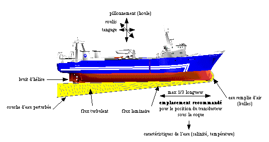 What disturbs depth measurement
What are the limits of a standard single-beam echo sounder?
Single-beam soundings with standard echo sounders, as in commercial fishing, have significant limits. The explanations below draw partly on information from Xavier Lurton, of Ifremer.
A fairly wide beam. The echo sounder sends a short signal vertically below the ship, in a conical beam that concentrates the energy on a circular area of the seabed. It measures the round-trip time of the signal, which gives the water depth.

The area lit by the beam must therefore be considered. For fishing echo sounders, it is limited either by the beam angle or by the signal duration. The signal is generally short (around a millisecond) for acceptable resolution: shorter in shallow water, for resolution, and longer in very deep water, to have more acoustic power available on reception.
But most fishing transducers transmit in a wide cone: from 7° (single-frequency) to 45° (dual-frequency) at 50 kHz, and from 7° (single-frequency) to 15° (dual-frequency) at 200 kHz (at −3 dB). Echo sounders designed for hydrography have much narrower beams, of 3 to 5°. Airmar, the main transducer supplier to echo sounder manufacturers, offers a full range for every use and budget.
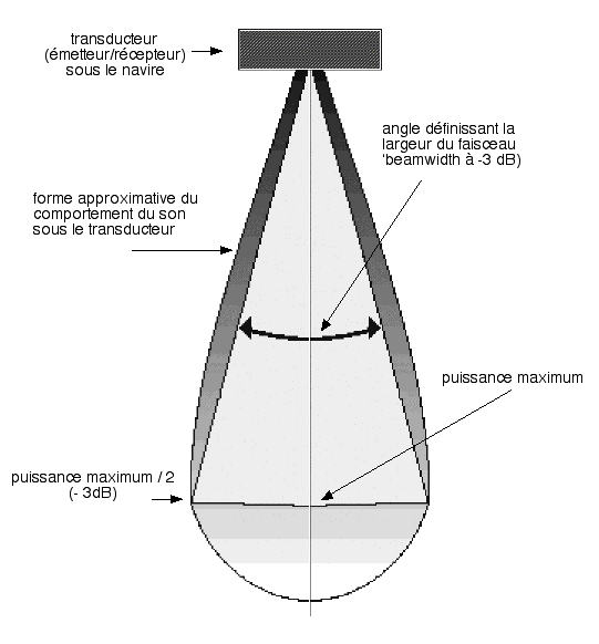 The beam
The diameter of the ensonified area increases with depth:
horizontal resolution = 2 × depth × tangent (cone angle / 2)
For a transducer with a 15° beam:
| Depth | 10 m | 30 m | 50 m | 100 m | 200 m |
|---|---|---|---|---|---|
| Diameter of the ensonified area | 2.6 m | 7.9 m | 13 m | 26 m | 53 m |
In deep water, is the displayed depth credible for bathymetric surveys? A 28 kHz “deep-water” echo sounder of several kilowatts can have a transducer with a narrow 7° beam. At 1,000 m, the ensonified area is then 122 m in diameter, nearly 12,000 m², the equivalent of two football pitches. Despite these limits, experience gives surprising results: although coarse, the surveys of deep-water echo sounders compare with multibeam surveys. Fishing captains have seen how Olex makes up for the lack of bathymetry on official charts and gives a better view of the seabed in these areas. See the work of the trawler Drake on terraces west of Ireland, in the user examples, and the multibeam surveys of the Thalassa in the same areas.
Choosing a narrow-beam transducer is therefore very important for bathymetry. For fishing, it also matters for fish detection: the narrower the beam, the more precise the target detection. To be told apart, two targets must be separated by at least the beam width at their depth.
The echo sounder keeps the earliest echo. Without angular discrimination, the echo sounder first receives the echo from the nearest point in the beam, which may be very different from the point vertically below the boat. The displayed value, and therefore the one sent over NMEA to a system such as Olex, is the minimum sounding measured, i.e. the start of the echo (other echo sounders average the echo samples). This is also a safety matter: by giving the highest point, the echo sounder warns the navigator of dangers and helps avoid grounding.
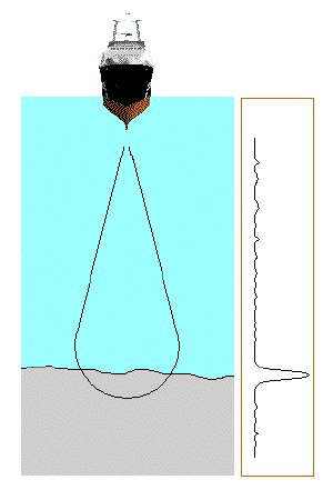 Flat seabed: the received signal is an attenuated copy of the transmitted signal
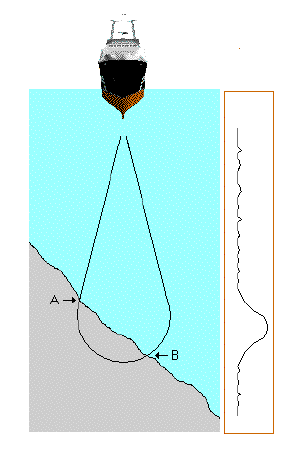 Sloping seabed: the received signal is longer, with slower rising and falling edges; the echo sounder gives
the depth at point A rather than vertically below the transducer
Sloping seabed: the received signal is longer, with slower rising and falling edges; the echo sounder gives
the depth at point A rather than vertically below the transducer
Moreover, as the slant range to the echo sounder changes while the boat moves, the echo recorded over time takes a parabolic shape (see the characteristic crescent-shaped fish detections on the echogram).
Single-beam surveys are therefore limited by their poor horizontal resolution, and the recorded relief contains many artefacts:
| Example 1 | Example 2 | Example 3 | |
|---|---|---|---|
| Relief | hollow narrower than the beam | hollow wider than the beam | peak or summit |
| Result | not detected, but the echo is stretched in time (hard to interpret) | detected, but its width is underestimated | detected, but its shape may be altered by the hyperbola effect |
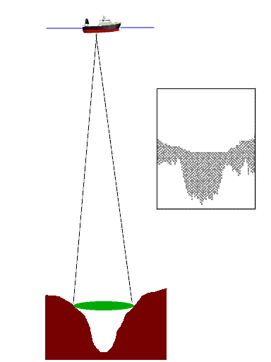 Example 1: hollow narrower than the beam
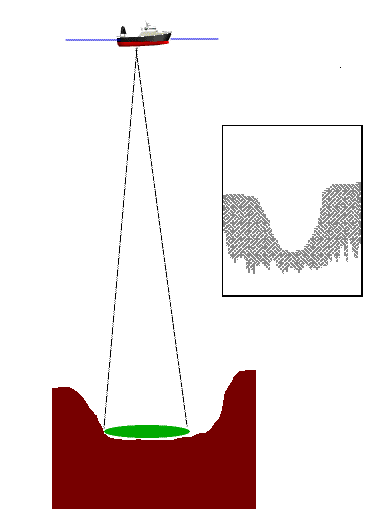 Example 2: hollow wider than the beam
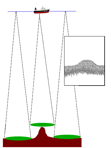 Example 3: peak or summit
Solutions. These effects are unavoidable with a single-beam echo sounder, which cannot distinguish anything within its beam. Another technology reduces them: by dividing the transducer face into several sectors, several beams are created that all see the target; the phase difference between these beams locates it in the horizontal plane. This process, called split-beam, is used in new echo sounders that are no longer reserved for fisheries research vessels. They show the seabed better, locate single fish and measure their target strength correctly.
Olex was the first system on the market to take advantage of these split-beam digital echo sounders: better measurement resolution, georeferenced echogram on the chart and indication of the seabed type. See Seabed hardness.
How can the speed of sound be corrected for temperature and salinity?
The speed of sound in water depends on temperature, salinity and depth. If this is ignored, the echo sounder gives wrong depths. For example:
- at 20 °C, the speed of sound is 1,482 m/s in distilled water and 1,522 m/s in seawater with 3.5% salinity;
- the speed of sound in water is taken to decrease by about 2.4 m/s when the temperature drops by one degree (around 25 °C);
- example formula: c (in m/s) = 1403 + 4.9 t − 0.05 t² + 0.16 p, where t is the temperature in °C and p the pressure in bars.
The speed of sound must therefore be measured for the conditions, or at least estimated as well as possible, to correct the soundings. As most vessels have neither a sound velocity profiler nor a salinity probe (CTD), it can be estimated with equations such as Coppens’.
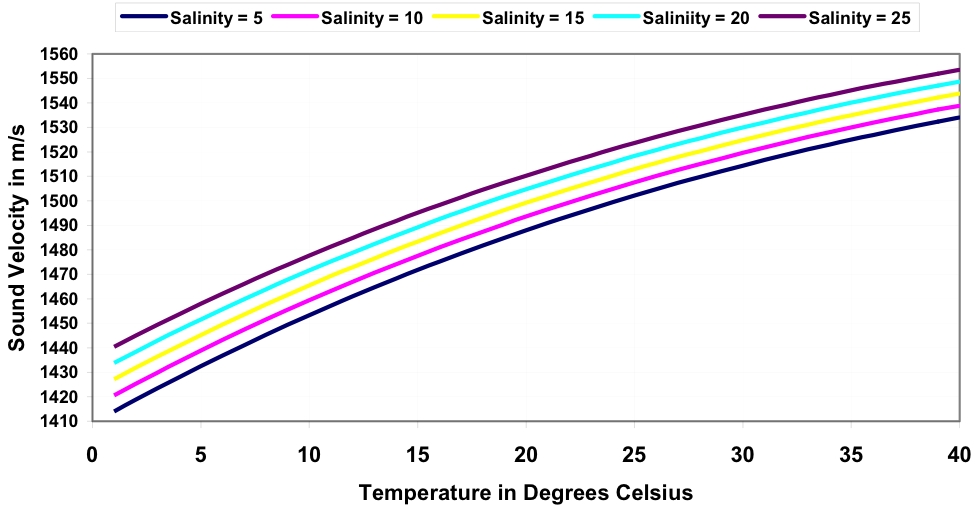 Effect of temperature on the speed of sound in water, for 5 salinities (Coppens equation, 1981)
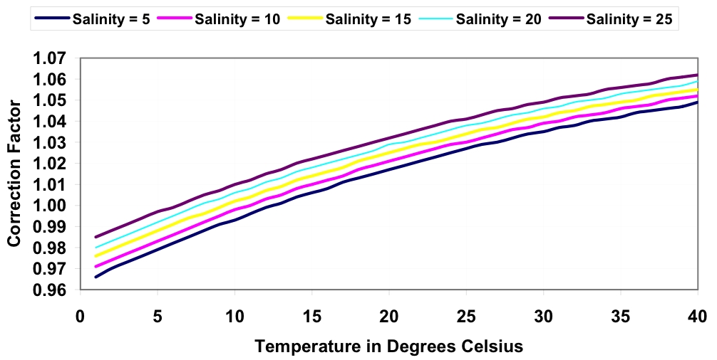 Effect of temperature on depth correction factors in seawater, for 5 salinities
Olex can apply a linear correction to the measured depth according to the difference between 1,500 m/s and the value V entered by the user, which must match the one used by the echo sounder:
corrected depth = acquired depth × V / 1,500
For example, with V = 1,470, the recorded depth is 2% lower, i.e. 0.667% per 10 m/s step. With the default value, 1,500 m/s, the depth is not changed.
This function also makes it possible, when importing or exporting soundings measured with different sound speeds, to bring them all to an average calibration of 1,500 m/s.
Installation and data
Can Olex be installed on a PC with other navigation software?
At the time of this answer, almost all fishing boats had an on-board computer with navigation software, and buying a second, backup PC was becoming common. But skippers used to a plotter for years were reluctant to switch systems, since it means training and changing habits.
Rather than buying the same software a second time, some customers chose different software that brings something new, without giving up their habits. The second bridge computer is set up for “dual boot”: by default it starts under Linux for Olex, but the user can start Windows for the other navigation software. Both systems coexist on the same machine with no loss of performance; for the setup, it is best to use a qualified Linux installer (contact us).
This is possible because, unlike other navigation systems running on Windows:
- Olex runs on a different operating system, Linux;
- Olex uses no electronic key (dongle) against illegal copying, only a software key.
The hard disk is split in two: a Windows partition and a Linux partition. At the time, Windows had to be installed before Linux, so this had to be planned from the start to avoid reinstalling everything. A backup of the navigation software and fishing plans from the first PC can then be copied to the Windows partition of the second PC.
Several customers used to another plotter for years thus bought Olex as a second system, first for its automatic real-time bathymetry. If the first PC fails, they can, with the second one:
- carry on with Olex and its navigation and mark-entry tools, if their fishing plans are kept up to date in it too;
- otherwise, or if Olex has only just been installed, restart under Windows to get back their usual software, after moving the dongle from the failed PC to the second PC.
In both cases, only one system runs at a time, the choice being made at start-up. This coexistence allows a smooth migration to Olex, safely, since the two environments remain completely independent, and with gradual learning. Some users have been won over by the simplicity of Olex beyond bathymetry, for example for entering fishing plans (automatic saving, no files or folders to manage), and have made it their main plotter.
Can fishing plans from another navigation system be converted to Olex format?
Yes, fishing plans from various navigation software can be converted to Olex format (see Services). Some users are indeed reluctant to re-enter their plans in Olex, despite the better GPS accuracy.
But MIS does not recommend this operation:
- it is of little technical value, since some data were entered with positioning less accurate than today’s GPS, others in an unknown geodetic datum;
- it is expensive for the user.
The first generation was that of video plotters, with basic charts and inaccurate hyperbolic positioning systems. The second generation, computer plotters, brought charts reproducing the official paper charts and more accurate satellite positioning: fishing plans had to be redone. With Olex, the third generation, users have vector charts in the international format of the hydrographic offices and GPS accuracy, which also allows real-time bathymetry. Thanks to its simple entry tools, Olex helps users sort through the information gathered over the years and bring their fishing plans up to date.
Updated : October 2026